Difference between revisions of "Simulink2ARM7"
(→Load the simulink model) |
|||
| Line 1: | Line 1: | ||
==Overview== | ==Overview== | ||
| − | This page describes the user interaction with the SimulinkTarget tool. Every step needed in order to get from Simulink Model to the Executable file is described in this page. The first step before getting the model to run in the ARM7 Board is to generate the code that implements the Simulink Model. This process is described here [[Simulink settings for generating code]] | + | This page describes the user interaction with the SimulinkTarget tool. Every step needed in order to get from Simulink Model to the Executable file is described in this page. The first step before getting the model to run in the ARM7 Board is to generate the code that implements the Simulink Model. This process is described here [[Simulink settings for generating code]]. |
==Create (or load) a project configuration file== | ==Create (or load) a project configuration file== | ||
| Line 36: | Line 36: | ||
==Load the RTW generated code== | ==Load the RTW generated code== | ||
| + | |||
| + | In order to complete this step, the user must first execute the [[Simulink settings for generating code]] and generate code with the Matlab Simulink Real-Time Workshop. | ||
[[image:simulinktarget05.jpg]] | [[image:simulinktarget05.jpg]] | ||
Revision as of 10:21, 15 April 2009
Contents
Overview
This page describes the user interaction with the SimulinkTarget tool. Every step needed in order to get from Simulink Model to the Executable file is described in this page. The first step before getting the model to run in the ARM7 Board is to generate the code that implements the Simulink Model. This process is described here Simulink settings for generating code.
Create (or load) a project configuration file
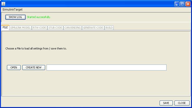
The SimulinkTarget tool creates a configuration file where all the decisions made during the conversion process are saved. Doing so enables the user to load the configuration file and avoids the overhead of going through all of the steps every time new code is generated. The first step is to either load or create a configuration file.
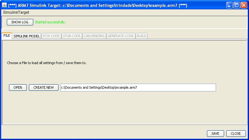
After loading/creating a configuration file, new tabs are enabled and the user may proceed to the next steps.
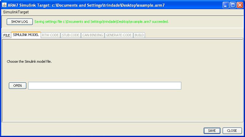
As the user can easily note, the tab Simulink Model has been enabled and is intuitively the next step to be taken.
Load the simulink model
The tool needs to load a Simulink Model in order to obtain model specific information, such as port names, model name, etc. After parsing the model necessary information is collected and the tool can go further. The first image shows the select model screen.
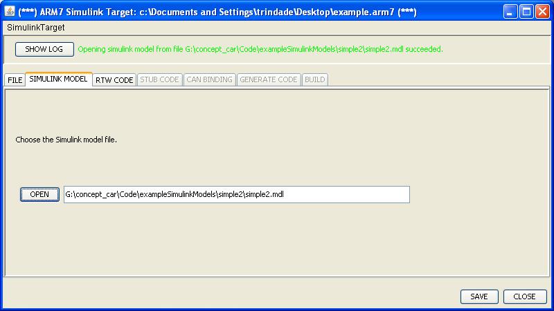
The user then selects the MDL file that contains the model that will be executed on the ARM7 platform.
Once again after completing the required steps inside the tab, new tabs are enabled and the user can continue to enter information required to achieve the final executable file.
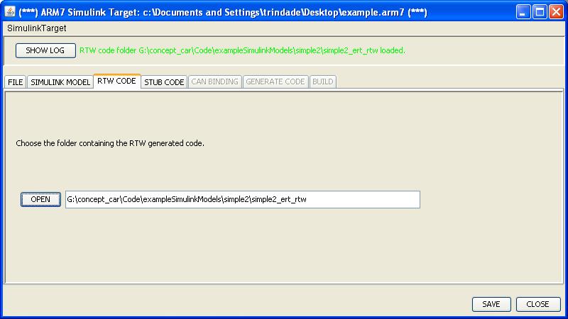
Load the RTW generated code
In order to complete this step, the user must first execute the Simulink settings for generating code and generate code with the Matlab Simulink Real-Time Workshop.
