Platform Specific Code Generation
Section 2.1 described how to generate the correspondent platform independent C code from a Simulink Model. As described previously, in order to get the code generated by RTW running on the target platform some glue code is necessary to access the run-time environments provided by the platform software. This Section describes the user actions required to get this code ready to execute on the target platform.
The SimulinkTarget Tool is used in this process. All the steps are described in the following.
Contents
- 1 Create (or load) a Project Configuration File
- 2 Load the Simulink Model
- 3 Load the RTW Generated Code
- 4 Select the Base Stub Code Used
- 5 Define CAN Binding and Marshalling
- 6 Define Output Folder and Generate Code
- 7 Optionally compile the generated code
- 8 Optionally compile the generated code manually
Create (or load) a Project Configuration File
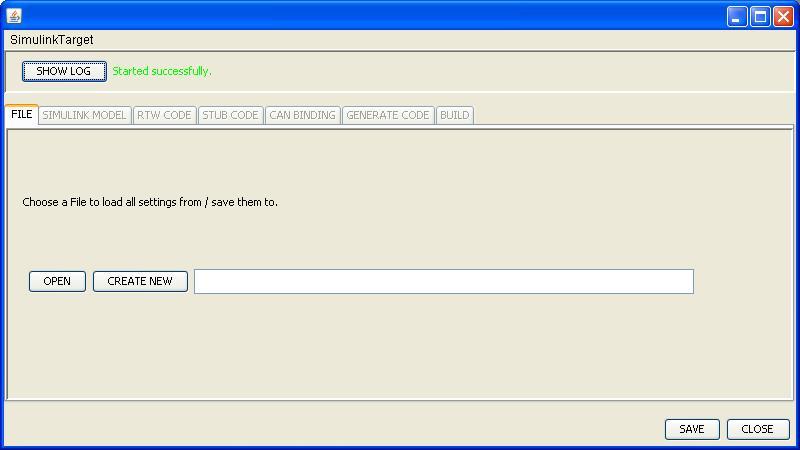
The SimulinkTarget tool creates a configuration file where all the decisions made during the conversion process are saved. Doing so enables the user to load the configuration file and avoids the overhead of going through all of the steps every time new code is generated. The first step is to either load or create a configuration file.
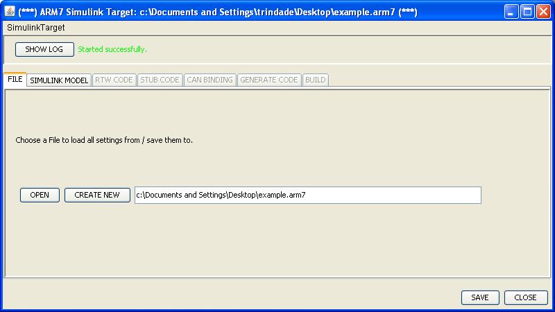
After loading/creating a configuration file, new tabs are enabled and the user may proceed to the next steps.
As the user can easily note, the tab Simulink Model has been enabled after load the Configuration File and is intuitively the next step to be taken.
Load the Simulink Model
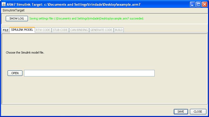
The tool needs to load a Simulink Model in order to obtain model specific information, such as port names, model name, etc. After parsing the model necessary information is collected and the tool can go further.
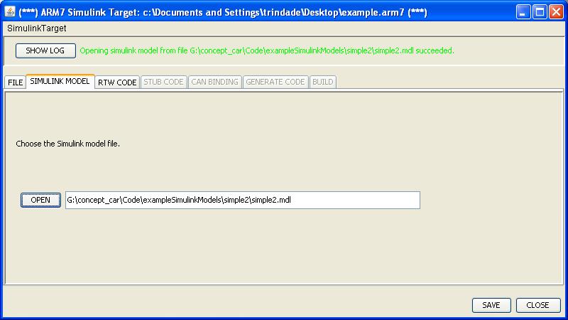
The user then selects the correspondent MDL file that contains the model that will be executed on the ARM7 platform.
Once again after completing the required steps inside the Simulink Model tab, new tabs are enabled and the user can continue to enter information required to achieve the final executable file.
Load the RTW Generated Code
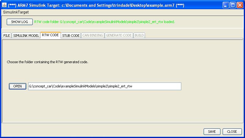
The goal of this step is load the code generated by the Matlab Simulink Real-Time Workshop. Therefore, in order to complete this step, the user must have finished the code generation using the Matlab Simulink Real-Time Workshop and have followed correctly all the Simulink settings for generating code presented in Section Setting the Simulink Model for code generation.
After the folder containing the RTW generated code is specified, the tool will merge the model code together with the base system code. The base system code is selected in the next step.
Select the Base Stub Code Used
The stub code contains both the base system functionality and the main system loop. The main system loop is responsible for the execution of the model.
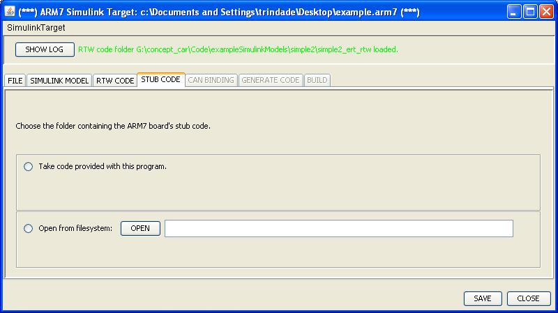
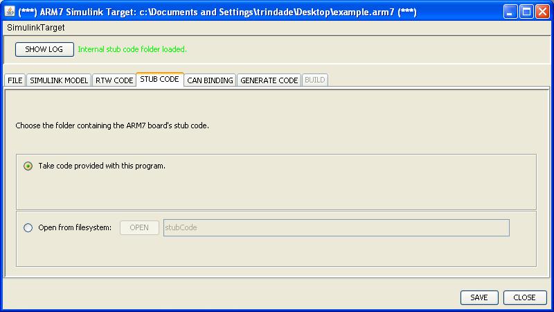
The screenshot above presents the user two options. One of them is to use the code provided with the SimulinkTarget tool. In this case the code used is related to a specific SVN release and will contain a version number. The user must be sure to use compatible combinations of software, that is, bootloader version should be the same as the stub code used with the SimulinkTarget.
In case the user has a copy of a newer code that either does not match the version provided by the tool or that is not yet a release, it is possible to select the second option. If this option is chosen, the user must provide the address of the folder containing the stub code.
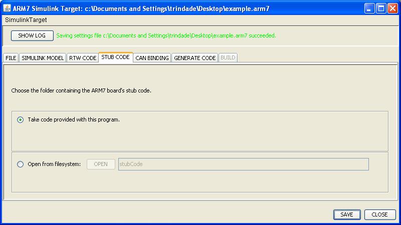
After selecting one of the two options two tabs are enabled. The user can thereafter walk through the final steps in the process of setting up the configuration for generating a binary executable. The figure below differs from the above regarding the status of the configuration file. After clicking the Save button the tool removes the asterisks from the title bar.
The base stub code provided by the tool or the user will be used together with the RTW generated code to compose the final source code, which will then be compiled into an application loaded by the ARM7 board bootloader.
Define CAN Binding and Marshalling
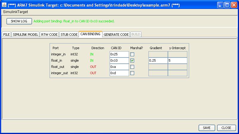
This part of the work flow defines the CAN port binding. Since in the Concept Car there is a CAN bus responsible for supplying a communication means to all of the boards in the network, all data is transmitted through it. When modeling functionality in a Simulink Data-Flow model, there is only reference to IN ports and OUT ports. The model does not describe how data is input and output to the ports. They are an open link to the environment where the model executes.
For this reason the user must provide a binding of the ports from the model to the Car's communication mechanism, which is a CAN bus. This is done by assigning CAN identifiers (IDs) to can messages that will carry the data to and from the model (more specifically, to/from the model ports).
The user is able to define (1) an ID, which will be automatically converted to a Hexadecimal value by the tool; (2) a gradient, which is used to transform the value that the message carries (e.g. to transform a floating point number into an integer number); and (3) a y-intercept parameter used to determine a scaling factor for the message value. These three fields are user configurable and the last two are optional. The optional fields are enabled by the checkboxes.
After defining the configurable fields for all ports the user can move on to the next step where the code will be generated. The information entered in this step by the user will be used during code generation. When the generator writes the code to get the value from the model (accessing the structure defined by the RTW generated code) it will then use the ID defined by the user to call the base CAN code to send the message on the bus.
The code generator figures the port variable names based on information from the Model and creates code to access them. After that, code is generated to send the values of the variables through the CAN bus using the IDs defined by the user.
Define Output Folder and Generate Code
At this point all the informations related to the code generation (merge between the RTW code and the base system code) are already setup. The next step is to select the destination folder and then the code is generated. The SimulinkTarget creates a folder named CODEGEN_yy-mm-dd_hh-mm-ss inside the selected destination folder.
The tool generates a header file that is used by the main execution loop. This header contains definitions about the name of the step function generated by RTW, information about the periodicity of the steps, etc. The user can check what kind of information is generated by opening the file "main.h" inside the folder "include/usr".
Optionally compile the generated code
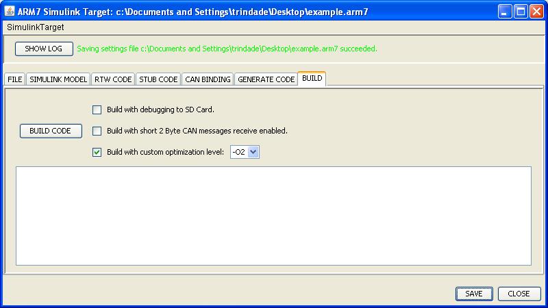
This is the last step in the work flow. Here the user can decide to compile the application within the tool. This step is optional because there is a makefile available for later compilation of the application. Nevertheless the user is able to select parameters for the compilation (such as debug information) and to deploy a binary executable through the SimulinkTarget tool. Figure 2.15 presents the screen to compile the generated code.
Optionally compile the generated code manually
You can also enter the folder where the code was generated and issue$ make simulink_canmanually. This will build the executable with no optimizations and no extra features.
